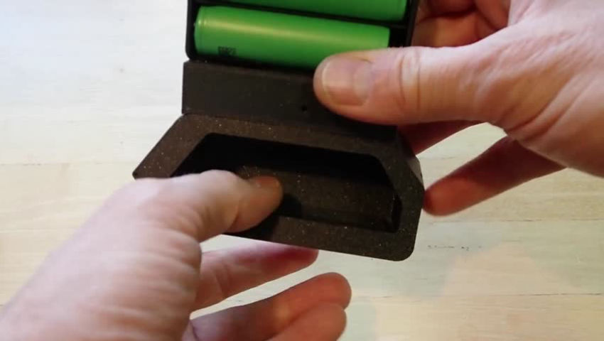
ExtremeDullard@lemmy.sdf.org to 3DPrinting@lemmy.worldEnglish · edit-212 hours agoCustom 3D-printed Flipper Zero extension enclosureplus-squaretoobnix.orgexternal-linkmessage-square0linkfedilinkarrow-up123arrow-down12
arrow-up121arrow-down1external-linkCustom 3D-printed Flipper Zero extension enclosureplus-squaretoobnix.orgExtremeDullard@lemmy.sdf.org to 3DPrinting@lemmy.worldEnglish · edit-212 hours agomessage-square0linkfedilink
ExtremeDullard@lemmy.sdf.org to 3DPrinting@lemmy.worldEnglish · 7 days agoUltra Smooth 3D Prints: Non-Planar Ironing on Standard Printers!plus-squareyoutu.beexternal-linkmessage-square0linkfedilinkarrow-up13arrow-down10
arrow-up13arrow-down1external-linkUltra Smooth 3D Prints: Non-Planar Ironing on Standard Printers!plus-squareyoutu.beExtremeDullard@lemmy.sdf.org to 3DPrinting@lemmy.worldEnglish · 7 days agomessage-square0linkfedilink
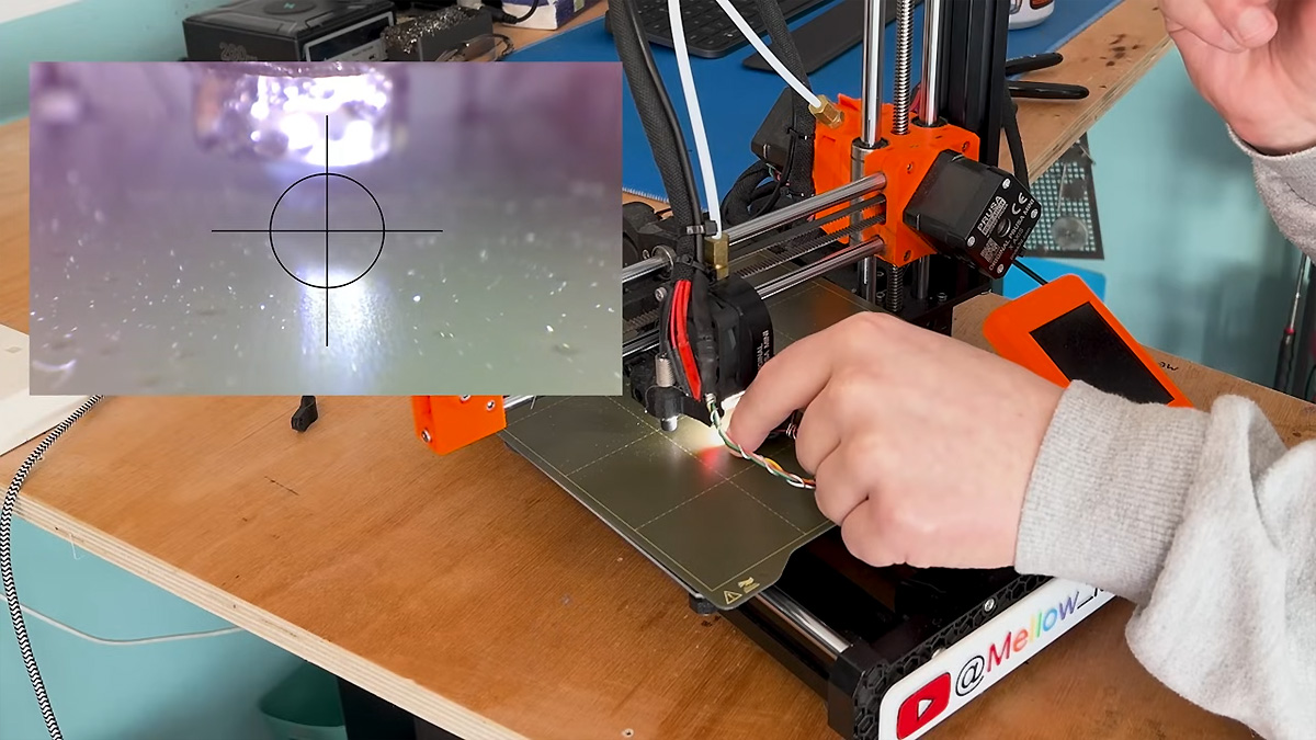
ExtremeDullard@lemmy.sdf.org to 3DPrinting@lemmy.worldEnglish · 11 days agoPrusa Mini Nozzle Cam On The Cheapplus-squarehackaday.comexternal-linkmessage-square0linkfedilinkarrow-up11arrow-down10
arrow-up11arrow-down1external-linkPrusa Mini Nozzle Cam On The Cheapplus-squarehackaday.comExtremeDullard@lemmy.sdf.org to 3DPrinting@lemmy.worldEnglish · 11 days agomessage-square0linkfedilink
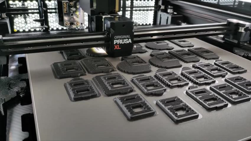
ExtremeDullard@lemmy.sdf.org to 3DPrinting@lemmy.worldEnglish · 13 days agoPrusa XL camplus-squaretoobnix.orgexternal-linkmessage-square0linkfedilinkarrow-up11arrow-down10
arrow-up11arrow-down1external-linkPrusa XL camplus-squaretoobnix.orgExtremeDullard@lemmy.sdf.org to 3DPrinting@lemmy.worldEnglish · 13 days agomessage-square0linkfedilink
ExtremeDullard@lemmy.sdf.org to 3DPrinting@lemmy.worldEnglish · 17 days agoBed slinger vs coreXY 3D printerplus-squaretoobnix.orgexternal-linkmessage-square0linkfedilinkarrow-up12arrow-down10
arrow-up12arrow-down1external-linkBed slinger vs coreXY 3D printerplus-squaretoobnix.orgExtremeDullard@lemmy.sdf.org to 3DPrinting@lemmy.worldEnglish · 17 days agomessage-square0linkfedilink
ExtremeDullard@lemmy.sdf.org to Privacy@lemmy.ml · 20 days agoOpen Home Foundationplus-squarewww.openhomefoundation.orgexternal-linkmessage-square0linkfedilinkarrow-up12arrow-down10
arrow-up12arrow-down1external-linkOpen Home Foundationplus-squarewww.openhomefoundation.orgExtremeDullard@lemmy.sdf.org to Privacy@lemmy.ml · 20 days agomessage-square0linkfedilink
ExtremeDullard@lemmy.sdf.org to 3DPrinting@lemmy.worldEnglish · 23 days agoR&D Tour: The engineering behind SLA/SLS Printersplus-squareyoutu.beexternal-linkmessage-square0linkfedilinkarrow-up11arrow-down10
arrow-up11arrow-down1external-linkR&D Tour: The engineering behind SLA/SLS Printersplus-squareyoutu.beExtremeDullard@lemmy.sdf.org to 3DPrinting@lemmy.worldEnglish · 23 days agomessage-square0linkfedilink
ExtremeDullard@lemmy.sdf.org to 3DPrinting@lemmy.worldEnglish · 24 days agoIs there enough filament to complete the print?plus-squaretoobnix.orgexternal-linkmessage-square0linkfedilinkarrow-up11arrow-down10
arrow-up11arrow-down1external-linkIs there enough filament to complete the print?plus-squaretoobnix.orgExtremeDullard@lemmy.sdf.org to 3DPrinting@lemmy.worldEnglish · 24 days agomessage-square0linkfedilink
ExtremeDullard@lemmy.sdf.org to 3DPrinting@lemmy.worldEnglish · 24 days agoThe Prusa Mk4 has done it again ☹️plus-squaretoobnix.orgexternal-linkmessage-square0linkfedilinkarrow-up11arrow-down10
arrow-up11arrow-down1external-linkThe Prusa Mk4 has done it again ☹️plus-squaretoobnix.orgExtremeDullard@lemmy.sdf.org to 3DPrinting@lemmy.worldEnglish · 24 days agomessage-square0linkfedilink
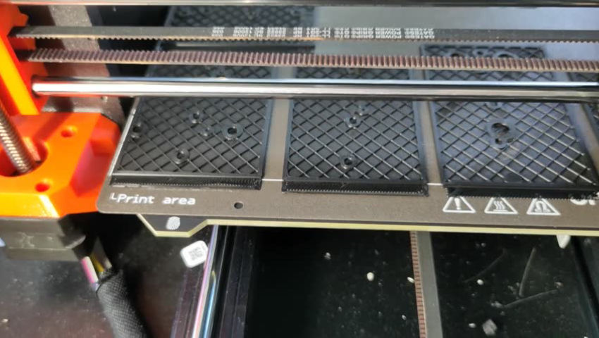
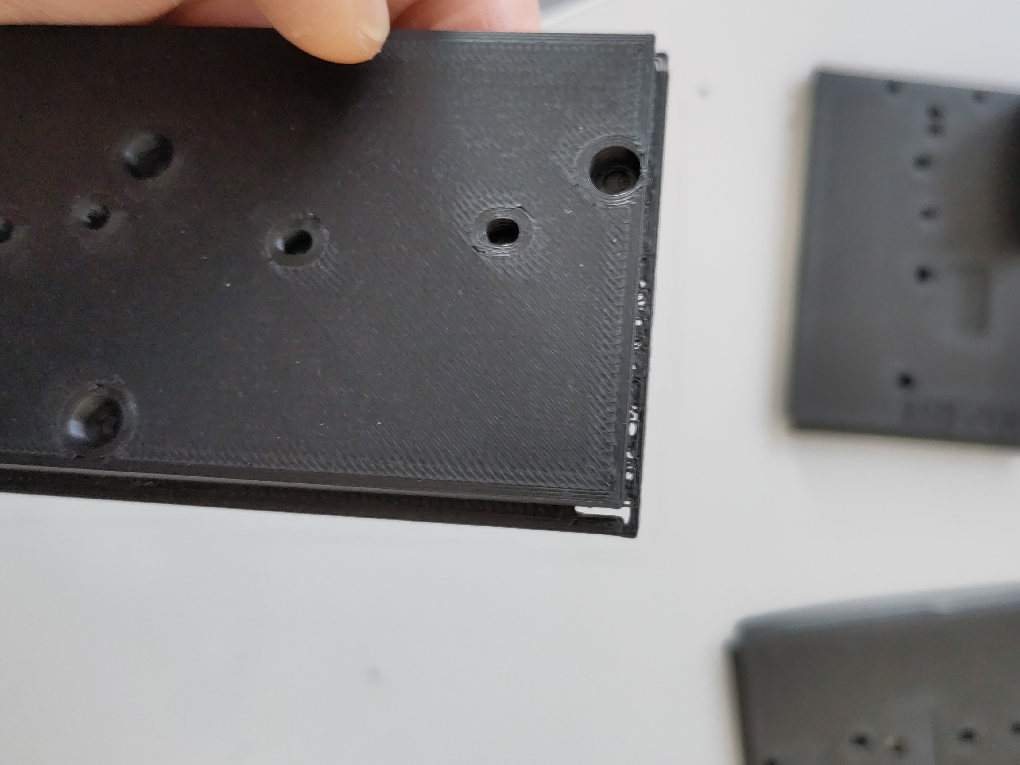
ExtremeDullard@lemmy.sdf.org to 3DPrinting@lemmy.worldEnglish · edit-225 days agoThe magnetic printing plate shifted early in the print - or something else happened?plus-squarelemmy.sdf.orgimagemessage-square0linkfedilinkarrow-up11arrow-down10
arrow-up11arrow-down1imageThe magnetic printing plate shifted early in the print - or something else happened?plus-squarelemmy.sdf.orgExtremeDullard@lemmy.sdf.org to 3DPrinting@lemmy.worldEnglish · edit-225 days agomessage-square0linkfedilink


